Pressure pneumatic conveyor system DFP
Description
Nowadays, pneumatic conveyor systems are used in many fields of the bulk goods industry. These goods range from dusty (Ø = 0–0.5 mm) to course-grained solids (Ø = >10 mm). The conveying capacity reaches from a few kilograms up to two hundred tons per hour or more.
The conveying pipe diameter varies from <50 mm to >500 mm. Conveying distances up to 1000 m can be reached.
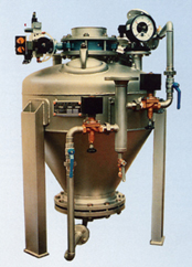
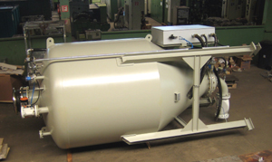
The pressure tank has become widely accepted for the pneumatic conveying with high pressure (big conveying distances) and a high concentration of goods (big conveying capacity).
In case of poorly flowing materials, it is possible to increase the conveying capability by special measures (cone aeration, mechanic discharging units).
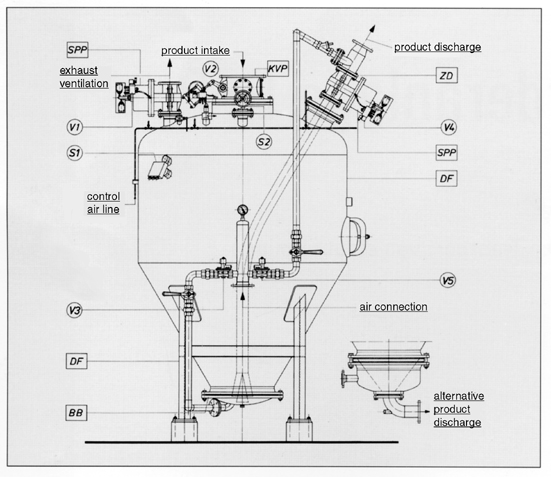
According to conveying material and conveying distance, center discharge by gravity (connection of conveying pipe below discharge cone) or top discharge (connection of conveying pipe from above to the standpipe rising into the pressure tank) as well as different pressure ratio of top, bottom or supplementary air inlet are chosen.
Loading of the pressure tank can be either done in free fall or by using suitable mechanic conveyors.
The pressure tank always works discontinuously. For that, a buffer tank is placed above the pressure tank when conveying continuous material. For bigger conveying capacities, two pressure tanks can be connected in parallel. During filling the first one, the second one will be emptied, and so, an almost continuous conveying can be reached. The average availability of a single pressure tank is 50%, and approx. 90% when two pressure tanks are connected in parallel.
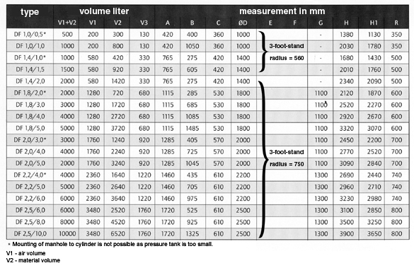
The conveying capacity of a pressure tank is defined by the net volume of the tank as well as by the diameter of the conveying pipe. Due to the different densities, grain sizes, grading and other physical caracteristics of bulk goods, it is not possible to give precise details on conveying capacity, even when pipe diameter and pressure tank volume (V1 + V2) are known.
Layout
The conveyor system consists of the pressure tank with all necessary instruments. It will be connected to the air pressure supply and the electric control.